Description
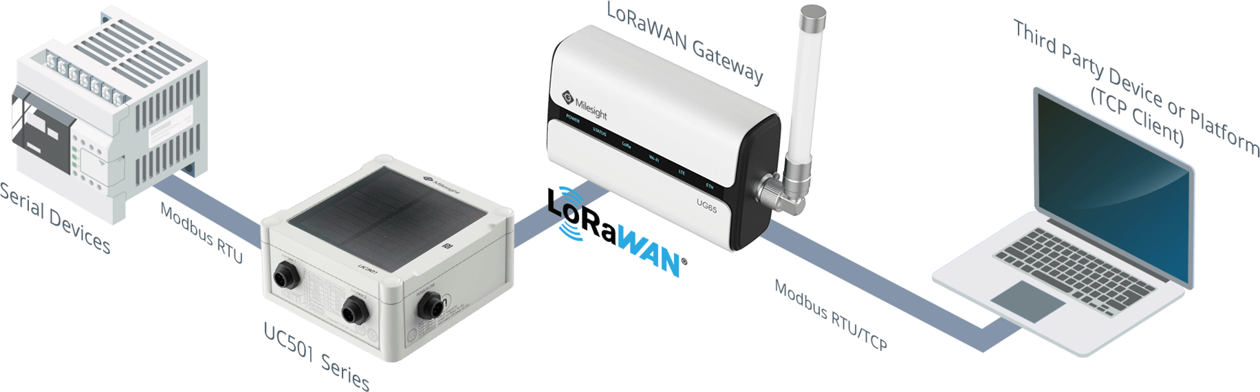
Modbus RTU bridge LoRaWAN is a feature which can set up Modbus-LoRaWAN data transmission between Milesight controllers and Modbus TCP/TCP clients via Milesight LoRaWAN gateways. The basic procedures are as follows:
- Send Modbus TCP/RTU reading or writing commands from a TCP client or Modbus TCP client
- Milesight gateways receive commands and translate them to Modbus RTU commands, then forward to Milesight controllers via LoRaWAN
- Milesight controllers receive and response the commands and return the results
- Milesight gateways receive the results and send to TCP client directly or translate to Modbus TCP results and send to Modbus TCP client
Requirements
- Milesight Controllers: UC501/UC11-N1-DC/UC1152
- Milesight UG6x/UG8xLoRaWAN Gateways (firmware version of UG8x should be above 80.0.0.34)
- ToolboxSoftware
- NetAssit (TCP Client simulate tool or Modbus Doctor (Modbus TCP client simulate tool)
- Modbus Slave or other Modbus RTU devices (meters, sensors, etc.)
Step-by-step:
1. Milesight Controller Configuration
2. Milesight Gateway Configuration
3. TCP Client/Modbus TCP Configuration
4.1 Transmission between Controllers and RS485 Devices
4.3 Send Query from TCP Client
Configuration
1. Milesight Controller Configuration
Before powering on Milesight controllers, please connect your Modbus RTU devices to RS485 port of controllers.
With Milesight controllers connected to PC with USB cable, open Toolbox. Select the USB port and type login password. The default password is 123456.

Navigate to General > RS485 page, enable Modbus RS485 bridge LoRaWAN and configure the port which is specified for bridging. In this example we use 200 as Modbus RS485 bridge LoRaWAN port.

Navigate to LoRaWAN page and select the working mode as Class C. You could also find essential attributes of the controllers and you would need them to register it onto Milesight gateways.

2. Milesight Gateway Configuration
Connect Milesight controllers to gateway following article How to Connect LoRaWAN Node/Sensor to Milesight Gateway. When registering devices in Network Server->Device page, select Modbus RTU Data transmission mode as required and type necessary information. If you connect TCP client to gateway and send Modbus RTU commands, select Modbus RTU over TCP; if you connect Modbus TCP client to gateway and send Modbus TCP commands, select Modbus RTU to TCP.
NOTE: Please type the Fport as Modbus RS485 bridge LoRaWAN port (In this example Fport is 200). TCP Port is used for allowing TCP client or Modbus TCP master connection.

3. TCP Client/Modbus TCP Configuration
3.1 TCP Client Configuration
Open NetAssist on PC, type in IP address of gateway as IP address of TCP server, Server Port should be the same as the TCP Port in gateway. Click Connect to connect the client to gateway.

3.2 Modbus TCP Configuration
Open Modbus Doctor on PC, type in IP address of gateway as IP address of Modbus TCP server, NumPort should be the same as the TCP Port in gateway. Click CLOSE, choose CONNECTION.

4. Test

Modbus over/to TCP share the same topology, except that the protocol in TCP client side is different. Testing Modbus over TCP is using original Modbus and TCP/IP. While testing Modbus to TCP we introduce Modbus TCP/IP (also Modbus-TCP) which is simply the Modbus RTU protocol with a TCP interface that runs on Ethernet.
4.1 Transmission between Controllers and RS485 Devices
Connect controller RS485 port to PC and stimulate serial data with Modbus Slave.

In Toolbox, configure a Modbus channel to poll data from Modbus Slave tool. If you can read data, the communication is on.

4.2 Send Query from Gateway
Use the following Modbus example to test the communication between gateway and controller.
Query frame:
| Slave ID | Function | Address | Length | Parity |
| 0x01 | 0x03 | 0x00 0x00 | 0x00 0x02 | 0xC4 0x0B |
Response frame:
| Slave ID | Function | Length | Data | Parity |
| 0x01 | 0x03 | 0x04 | 0x00 0x01 0x00 0x02 | 0x2A 0x32 |
Go to Network Server > Packets page, put in controller Device EUI and Port 200, select type as hex, then click Send to send Modbus command to controller.

A: gateway sends Modbus downlink successfully
B: Reply from controllers
C: ACK package from controllers
The details of reply packet is shown below:

4.3 Send Query from TCP Client
Send Modbus RTU format command 010300000002c40b to read first two digit of data, gateway (TCP server) will respond the Modbus reply 010304000100022A32.

In web GUI of gateway, you can check the details that sending the message from TCP client and receiving the replies from controllers.

Click the exclamation mark to see packets details, payload in hex matches what TCP client receives and is correctly “1,2”.

4.4 Read to Modbus TCP
Enable SPY MODE and click CONNECTION, see it’s printed in status:
Status: Connecting to 192.168.23.226:9099...
Status: Connected
As Modbus Slave has 10 addresses for default so we set Length as 10 too, click READING. You can see the query frame in darker blue and response frame in lighter one in the traffic communication block on the right.

Here is a data table of Modbus TCP communication protocol.
| Query Frame | Response Frame | ||
| Byte | Content | Byte | Content |
| 0-4 | Start | 0-4 | Start |
| 5 | Whole Length | 5 | Whole Length |
| 6 | Slave ID | 6 | Slave ID |
| 7 | Function Code | 7 | Function Code |
| 8, 9 | Start Address | 8 | Data Length |
| 9, 10 | Data | ||
| 10, 11 | Address Length | 11, 12 | Data |
| ... | Data | ||
According to the table we can tell the data read from Modbus RTU is 1,2 which is correct. In web GUI of gateway, you can check the details that sending the message from TCP client and receiving the replies from controllers.
4.5 Write from Modbus TCP
Modbus Doctor supports writing to Modbus RTU. You can input random number in Value of each Register, click WRITING. You can read the communication traffic according to the table above.

In Modbus Slave, you can see the value has changed correspondingly.

Was this article helpful?
That’s Great!
Thank you for your feedback
Sorry! We couldn't be helpful
Thank you for your feedback
Feedback sent
We appreciate your effort and will try to fix the article